


Multi-story building plumbing is defined by three interdependent systems: pressurized water supply zones, vertical drainage stacks, and coordinated venting networks that protect trap seals across every floor. Understanding how multi story building plumbing works is not optional for developers, architects, or construction professionals. Get any one of these three systems wrong and the entire building suffers, from low pressure on the top floor to sewer gas intrusion in occupied units. This guide breaks down each system with the engineering specifics you need for effective project planning.
How does water supply work in multi-story buildings?
Water pressure management is the defining engineering challenge in multi story plumbing systems. Pressure drops approximately 1 psi for every 2.31 feet of elevation. That means a 10-story building with 12-foot floor-to-floor heights loses roughly 52 psi from ground level to the top floor. Without active pressure management, upper floors receive inadequate flow and lower floors face damaging overpressure.
Pressure zones: the foundation of vertical supply design
The industry-standard solution is pressure zoning. Multi-story buildings segment water pressure into zones covering approximately 8–12 floors each, with dedicated booster pumps and pressure control equipment assigned per zone. This approach prevents energy waste and isolates pressure conditions, making troubleshooting far more manageable when issues arise.
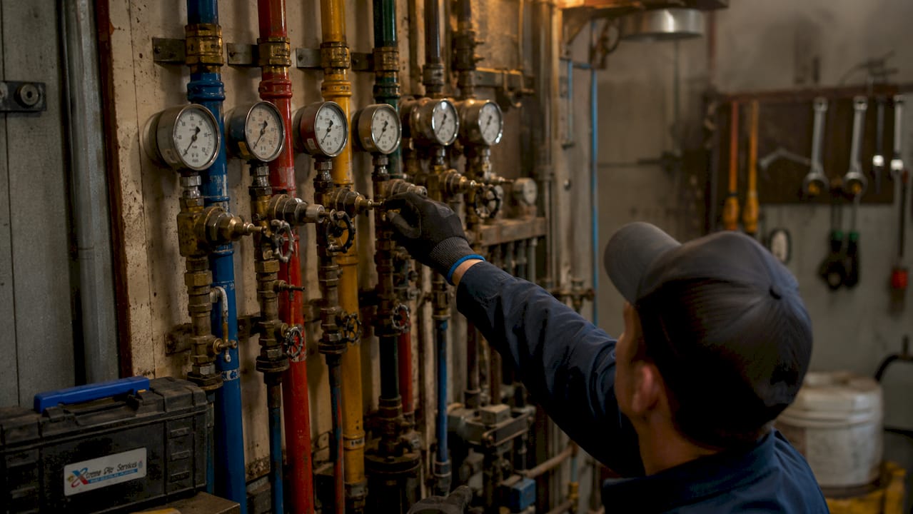
Each zone operates as a self-contained pressure circuit. A booster pump set feeds the zone from below, and pressure reducing valves (PRVs) cap the maximum pressure delivered to fixtures. The IRC 2024 requires PRV installation when static pressure exceeds 80 psi, with downstream pressure set between 60 and 80 psi to protect fixtures and piping. Setting PRVs conservatively at 60–70 psi downstream creates an operating margin that reduces system wear during supply pressure fluctuations.
Booster pumps, break tanks, and pressure control
Booster pump sets are the workhorses of vertical plumbing design in any building above four or five stories. Two common configurations exist: direct-boost systems that pressurize cold water directly from the main supply, and break-tank arrangements that store water at atmospheric pressure before re-pressurizing it for distribution.
Break tanks and booster pump sets create complex pressure control schemes in tall buildings above 20 stories. Intermediate break tanks are not simply an efficiency measure. They are a resilience strategy that prevents water hammer and limits maximum static pressure on lower-zone piping. Without them, a single pressure event can stress fittings across dozens of floors simultaneously.
Key components in a well-designed supply zone include:
- Booster pump sets sized for peak demand flow rates per zone
- Pressure reducing valves positioned downstream of the meter and upstream of first branch connections
- Break tanks at intermediate mechanical floors to reset pressure baselines
- Pressure gauges and isolation valves at each zone entry point for maintenance access
- Backflow preventers to protect the municipal supply from contamination
Pro Tip: When sizing booster pumps, account for simultaneous fixture demand at peak occupancy, not average daily use. Undersized pumps are the most common cause of pressure complaints in newly occupied residential towers.
What is a plumbing riser diagram and why does it matter?
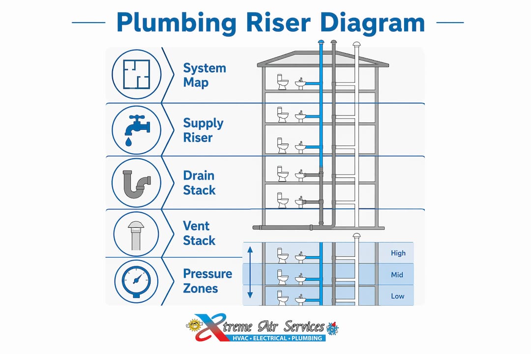
A plumbing riser diagram is the system map that every engineer, contractor, and inspector relies on throughout a building’s life. Riser diagrams illustrate vertical pipes and branch connections per floor, annotating PRV locations and distinct pressure zones for clarity in design and construction. Without an accurate riser diagram, onsite adjustments risk destabilizing pressure across zones and creating failures that are difficult to trace.
What a riser diagram shows
A riser diagram is a schematic, not a physical drawing. It represents the building’s plumbing in a vertical cross-section, showing how supply and drainage pipes travel from the plant room at the base through mechanical floors to individual units at the top. Here is what a complete riser diagram must document:
- Cold and hot water supply risers with pipe sizes annotated at each branch takeoff
- PRV locations with upstream and downstream pressure values noted
- Pressure zone boundaries clearly marked by floor range
- Booster pump and break tank locations on mechanical floors
- Drainage stack paths with stack sizes and vent connections shown
- Individual tenant isolation valves and meters for multi-occupancy buildings
The table below shows how riser diagram elements map to their function in the overall system:
| Riser Diagram Element | System Function |
|---|---|
| Supply riser with pipe size | Determines flow capacity to each floor zone |
| PRV annotation | Confirms pressure is reduced before fixture branches |
| Pressure zone boundary | Defines where one booster circuit ends and another begins |
| Drainage stack path | Shows waste flow route and vent connection points |
| Tenant isolation valve | Allows unit shutoff without affecting the whole building |
| Vent stack connection | Confirms airflow path for trap seal protection |
Using riser diagrams during construction and troubleshooting
Riser diagrams serve two distinct purposes. During construction, they guide installation sequencing and help MEP (mechanical, electrical, and plumbing) trades coordinate pipe routing through shared shafts. During operation, they become the first reference point when pressure complaints or drainage failures occur. A technician who can read the riser diagram can identify which zone a failing fixture belongs to and isolate the problem without disrupting the rest of the building.
Pro Tip: Require as-built riser diagrams to be updated after any system modification. Original design drawings become inaccurate the moment a contractor makes a field change, and outdated diagrams cause misdiagnosis during maintenance calls years later.
How does drainage and venting work in tall buildings?
Drainage in multi-story buildings relies on gravity, but venting is what makes gravity drainage reliable. Drain stacks in tall buildings entrain air as wastewater falls, creating negative pressure that can siphon trap seals and allow sewer gas into occupied spaces. Venting systems counteract this by supplying air to the drainage network at controlled points.
Trap-to-vent distances and code requirements
The International Plumbing Code (IPC) specifies maximum horizontal distances between a trap and its vent connection. These distances range from 5 feet for 1¼-inch traps to 16 feet for 4-inch traps. Exceeding these distances requires alternative venting methods such as wet venting, circuit venting, or air admittance valves (AAVs).
Trap seal protection against negative pressure is the fundamental driver behind venting requirements. Code compliance is the floor, not the ceiling. A design that barely meets static vent distance requirements can still fail if dynamic airflow conditions during peak drainage loads are not considered.
Stack height limits and auxiliary vent solutions
Single-stack drainage configurations work well up to a point. Single-stack systems are generally limited to 10–20 floors before the air entrainment from falling wastewater creates negative pressures that standard venting cannot manage. Beyond that height, designers must add auxiliary vent stacks or secondary drainage stacks.
The comparison below shows how venting strategies differ by building height:
| Building Height | Venting Strategy | Key Risk |
|---|---|---|
| 1–5 floors | Individual vent pipes per fixture group | Minimal; standard code compliance sufficient |
| 6–10 floors | Vent stack with branch vents per floor | Moderate; stack sizing becomes critical |
| 11–20 floors | Single-stack with intermediate relief vents | Higher; requires careful airflow calculation |
| 20+ floors | Auxiliary vent stacks or dual-stack systems | Significant; negative pressure management is primary concern |
Air admittance valves (AAVs) offer a practical solution in locations where running a full vent stack to the roof is not feasible. AAVs open under negative pressure to admit air, then close to prevent sewer gas escape. They are widely accepted under the IPC for individual fixture venting but are not a substitute for a primary vent stack in high-rise applications.
Pro Tip: Coordinate vent stack terminations with the mechanical engineering team early. Vent pipes that terminate near HVAC air intakes create sewer gas contamination problems that are expensive to fix after construction.
What are the biggest challenges in multi-story plumbing design?
Multi-occupancy building plumbing success depends on integrated design from the plant room through risers to individual apartments. Treating each apartment’s plumbing as an isolated system is the most common and costly mistake in multi-level plumbing layout. Pressure inconsistency and hot-water performance failures during peak demand are the predictable result.
System integration from plant room to fixture
The plant room is where the entire building’s water supply originates. It houses the break tanks, booster pump sets, hot water generation equipment, and primary isolation valves. Every decision made in the plant room propagates through the risers to every fixture in the building. Undersized plant room equipment cannot be compensated for by adjustments at the riser level.
Integrated design means the MEP engineer models the system as a single network, not as separate zones that happen to share a building. Flow velocity in risers, pressure loss through fittings, and heat loss in hot water distribution all interact. A pipe material selection decision made early in design affects both pressure performance and long-term maintenance costs.
Common operational challenges and how to avoid them
Plumbing challenges in tall buildings cluster around a few recurring failure modes:
- Water hammer caused by rapid valve closure in high-pressure zones. Specify slow-close solenoid valves and install hammer arrestors at appliance connections.
- Thermal expansion in hot water risers that stresses joints over time. Design expansion loops or use flexible connections at riser offsets.
- Pressure creep below PRVs when PRVs are not maintained. Schedule annual PRV testing as part of the building’s plumbing maintenance program.
- Trap seal loss during low-occupancy periods when drainage flow is insufficient to maintain airflow balance. AAVs or wet venting can address this in residential towers with variable occupancy.
- Cross-connection between cold and hot supply risers in shared shaft configurations. Require pressure testing of each riser independently before connecting to the distribution network.
Dynamic flow conditions are where many designs that look correct on paper fail in practice. A vent distance that meets IPC requirements under static conditions can still allow trap siphonage when multiple fixtures discharge simultaneously on adjacent floors. Modeling peak simultaneous demand is not optional for buildings above 10 stories.
Fire suppression systems add another layer of complexity. The fire suppression plumbing network shares building shafts with domestic plumbing but operates under completely different pressure and flow requirements. Coordination between the plumbing engineer and the fire protection engineer must happen at schematic design, not during construction documents.
Key takeaways
Effective multi-story building plumbing design requires pressure zoning, accurate riser diagrams, and coordinated venting to deliver reliable water supply and safe waste removal across every floor.
| Point | Details |
|---|---|
| Pressure zoning is non-negotiable | Zone every 8–12 floors with dedicated booster pumps and PRVs to maintain safe fixture pressure. |
| Riser diagrams drive every decision | Accurate, updated riser diagrams are the foundation for installation, coordination, and troubleshooting. |
| Venting protects occupants | Single-stack systems are limited to 10–20 floors; taller buildings require auxiliary vent stacks or dual-stack configurations. |
| Break tanks prevent overpressure damage | Intermediate break tanks in towers above 20 stories limit static pressure and prevent water hammer. |
| Integrated design prevents failures | Treating apartment plumbing as isolated systems causes pressure inconsistency and peak-demand failures. |
What i’ve learned designing plumbing for multi-story buildings
After working on multi-story plumbing projects across residential towers and commercial buildings, the pattern I see most often is this: pressure zoning gets the engineering attention it deserves, but venting gets treated as an afterthought. Teams spend weeks modeling booster pump curves and PRV settings, then hand off the vent stack layout to a junior drafter with a code book. That is where buildings fail.
The trap seal is the last line of defense between occupied space and the sewer system. A design that passes code review can still allow sewer gas intrusion if the airflow dynamics during peak drainage are not modeled. I have seen this happen in a 15-story residential building where the vent stack was correctly sized for individual fixture loads but not for the simultaneous discharge of 30 units during morning peak hours. The fix required core drilling through three mechanical floors after the building was occupied. That is an expensive lesson.
The other thing I would push back on is the idea that riser diagrams are just documentation. They are design tools. The act of drawing a riser diagram forces the engineer to reconcile pressure zones, pipe sizes, and vent connections in a single view. Problems that hide in plan drawings become obvious in a riser diagram. Require them early, update them always, and make sure the building owner receives a final as-built version at handover.
The future of multi-story plumbing is moving toward pressure-independent control valves and real-time monitoring of zone pressures via building management systems. These tools do not replace good engineering judgment. They make it easier to catch drift before it becomes a failure.
— Xtreme
Professional multi-story building plumbing services
Multi-story building plumbing systems require precision at every stage, from plant room design through riser installation to final fixture connections. Xtremeairservices provides professional plumbing services for residential and commercial buildings of all sizes, including pressure zone design, booster system installation, and full drainage and venting work. Our team understands the coordination demands of multi-level plumbing layout and works directly with architects and developers to keep projects on schedule.

Whether you are planning a new multi-story development or troubleshooting an existing system, Xtremeairservices has the technical depth to get it right. Contact us to discuss your project requirements and learn how our plumbing and building services can support your next build from the ground up.
FAQ
How many pressure zones does a multi-story building need?
Most buildings use one pressure zone per 8–12 floors, each served by its own booster pump and PRV set. A 30-story building typically requires three separate pressure zones to maintain safe fixture pressure throughout.
What causes low water pressure on upper floors?
Pressure drops approximately 1 psi for every 2.31 feet of elevation, so upper floors lose significant pressure without booster pumps. Undersized booster pumps or incorrectly set PRVs are the most common causes of low pressure complaints in occupied towers.
How do plumbing stacks function in high-rise buildings?
Drainage stacks carry wastewater by gravity from upper floors to the building drain at the base. Falling water entrains air and creates negative pressure, which is why vent stacks run parallel to drain stacks to maintain airflow balance and protect trap seals.
When are auxiliary vent stacks required?
Single-stack drainage configurations are generally limited to 10–20 floors before negative pressure risks become unmanageable. Buildings taller than 20 stories require auxiliary vent stacks, secondary drainage stacks, or intermediate relief vents to maintain trap seal integrity.
What is the purpose of a break tank in a tall building?
A break tank stores water at atmospheric pressure before a booster pump re-pressurizes it for the next zone. In buildings above 20 stories, intermediate break tanks limit maximum static pressure on lower-zone piping and prevent water hammer caused by pressure surges.
Recommended
- How your House Plumbing Works – YouTube
- The Role Of Fire Suppression Plumbing For Property Owners
Need professional help? Explore our commercial plumbing services.